

E-mail:
david@wuyunconveyor.com

REQUEST A QUOTE
ENG
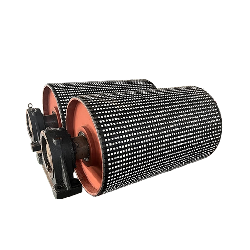
The Conveyor Ceramic Lagging Pulley is designed for belt conveyor systems requiring enhanced belt traction and high resistance to pulley surface wear. Its pulley surface is equipped with ceramic lagging to increase friction between the pulley and conveyor belt, helping reduce belt slippage and maintain stable belt operation.
The ceramic lagging provides excellent resistance to abrasion and can withstand friction and impact from rough bulk materials. It is particularly suitable for demanding conveyor applications where conventional pulley surfaces may experience accelerated wear.
Key Features
Ceramic Lagging Surface
The pulley is equipped with a ceramic lagging surface that provides enhanced resistance to abrasion and wear during continuous conveyor operation.
High Belt Traction
Ceramic lagging increases friction between the pulley and conveyor belt, helping improve grip and reduce belt slippage.
Abrasion Resistance
The ceramic surface is designed to withstand continuous friction and impact from abrasive bulk materials, helping extend pulley service life.
Corrosion Resistance
The ceramic surface provides resistance to corrosion, making the pulley suitable for demanding material handling environments.
Stable Conveyor Operation
Improved pulley-to-belt friction helps maintain stable belt movement and reliable conveying performance.
Product Advantages
Higher belt traction: Ceramic lagging provides strong friction between the pulley and belt, helping reduce slippage.
Excellent wear resistance: The ceramic surface withstands friction and impact from abrasive materials.
Extended pulley service life: High surface durability helps reduce premature pulley wear and replacement frequency.
Reduced belt slippage: Improved pulley-to-belt grip supports stable power transmission.
Suitable for demanding conditions: Ceramic lagging is suitable for abrasive and challenging bulk material conveying applications.
Improved operating reliability: Stable belt contact helps maintain consistent conveyor performance.
Applications
The Conveyor Ceramic Lagging Pulley is mainly used on belt conveyor systems where high belt traction and resistance to abrasive wear are required. Ceramic pulley lagging is particularly valuable in demanding applications involving abrasive materials or conditions where belt slippage can affect conveyor performance. Industry suppliers commonly position ceramic lagging for drive pulleys and other pulley positions where increased grip and wear resistance are required.
Typical applications include:
Mining and Quarrying: For conveyors handling ores, aggregates, crushed stone, and other abrasive bulk materials.
Steel and Metallurgy: For demanding material handling systems where pulley surface wear is a major concern.
Cement and Building Materials: Suitable for abrasive bulk material conveying and continuous conveyor operation.
Ports and Bulk Material Handling: Used where reliable belt traction and durable pulley surfaces are required.
Heavy-Duty Conveying: Suitable for conveyor systems exposed to high friction, material impact, and continuous wear.
Wet or Muddy Material Handling: Ceramic lagging can provide increased grip in operating conditions where belt slippage is a concern.
Ordering & Quotation Information
Information Required for Quotation
Please provide the pulley diameter, face width, shaft dimensions, conveyor belt width, installation position, required quantity, and operating conditions. Belt tension, traction requirements, abrasive material conditions, and existing pulley information are useful for confirming ceramic lagging requirements.
Technical Confirmation & Lead Time
We will confirm the pulley configuration according to drive arrangement, traction requirements, belt tension, pulley dimensions, shaft arrangement, and installation interface. Lead time depends on specifications, quantity, ceramic lagging requirements, material preparation, and purchased components.
Packaging, Delivery & Quality
Packaging and delivery are arranged according to pulley dimensions, weight, quantity, transportation method, and destination. Dimensions, shaft configuration, lagging condition, quantity, and packaging are checked before shipment.
FAQ
What is a Conveyor Ceramic Lagging Pulley?
A Conveyor Ceramic Lagging Pulley is a conveyor pulley equipped with ceramic lagging on its surface to improve belt traction and provide high resistance to surface wear.
What is the purpose of ceramic pulley lagging?
Ceramic pulley lagging increases friction between the pulley and conveyor belt, helping reduce belt slippage while providing enhanced abrasion resistance.
Is ceramic lagging suitable for abrasive materials?
Yes. Ceramic lagging is commonly used in demanding conveyor applications involving abrasive materials because of its high wear resistance.
Can ceramic lagging reduce belt slippage?
Yes. The ceramic surface increases belt-to-pulley grip and can help reduce belt slippage, particularly in demanding or wet conveying conditions.
Where is ceramic lagging commonly used?
It is commonly used in mining, quarrying, ports, steel, cement, and other bulk material handling applications where high traction and wear resistance are required.
What is the difference between a standard lagged pulley and a ceramic lagging pulley?
A standard Conveyor Lagged Pulley can use rubber, ceramic, or polyurethane lagging, while a Conveyor Ceramic Lagging Pulley specifically uses ceramic lagging to emphasize higher wear resistance and increased belt traction.
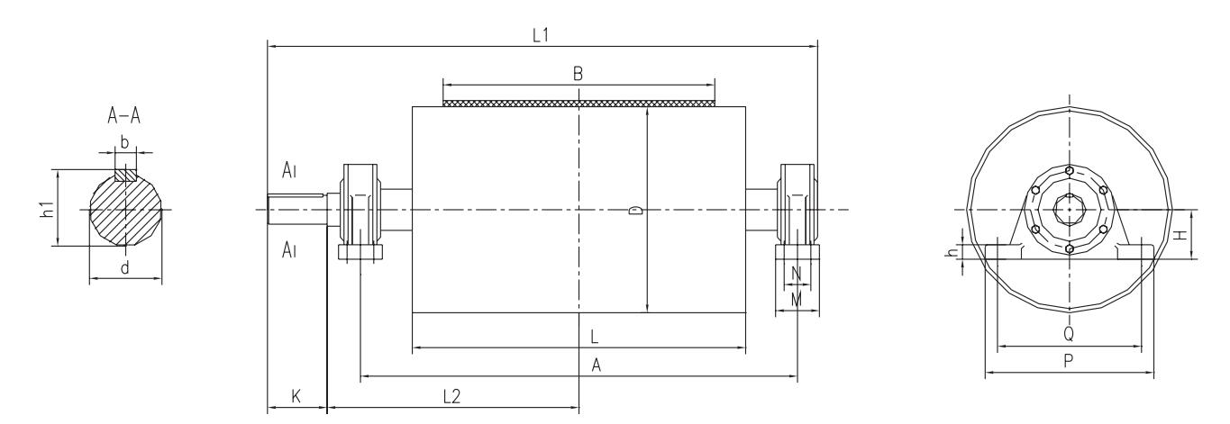
Unit: mm
| B | D | A | L | L1 | L2 | K | M | N | Q | P | H | h | h1 | d | b | ds | Bearing | Allowable torque (kg/mm) |
Drawing No | |||
| Smooth surface |
Adhesive surface |
Smooth surface |
Casting glue |
Coated with adhesive |
||||||||||||||||||
| 500 | 500 | 850 | 600 | 1097 | 505.5 | 115 | 70 | — | 280 | 340 | 100 | 33 | 60 | 55 | 16 | 27 | 1312 | 16300 | 25000 | TD1A13 | TD1A23 | TD1A33 |
| 650 | 500 | 1000 | 750 | 1280 | 588.5 | 135 | 90 | — | 350 | 410 | 120 | 33 | 76 | 70 | 20 | 1316 | 21200 | 32600 | TD2A13 | TD2A23 | TD2A33 | |
| 630 | 29600 | 45400 | TD2A14 | TD2A24 | TD2A34 | |||||||||||||||||
| 800 | 500 | 1300 | 950 | 1580 | 738.5 | 135 | 90 | — | 350 | 410 | 120 | 33 | 76 | 70 | 20 | 1316 | 26200 | 40100 | TD3A13 | TD3A23 | TD3A33 | |
| 630 | 1661 | 771 | 175 | 130 | 80 | 380 | 460 | 140 | 33 | 97 | 90 | 24 | 3520 | 36700 | 56100 | TD3A14 | TD3A24 | TD3A34 | ||||
| 800 | 55900 | 85500 | TD3A15 | TD3A25 | TD3A35 | |||||||||||||||||
| 1000 | 630 | 1500 | 1150 | 1861 | 871 | 175 | 130 | 80 | 380 | 460 | 140 | 33 | 97 | 90 | 24 | 3520 | 45700 | 70100 | TD4A14 | TD4A24 | TD4A34 | |
| 800 | 1945 | 900 | 215 | 160 | 90 | 440 | 530 | 160 | 53 | 119 | 110 | 32 | 34 | 3524 | 69600 | 106800 | TD4A15 | TD4A25 | TD4A35 | |||
| 1000 | 2020 | 930 | 255 | 170 | 100 | 480 | 570 | 180 | 53 | 140 | 130 | 36 | 3528 | 177500 | — | TD4A26 | TD4A36 | |||||
| 1200 | 630 | 1750 | 1400 | 2195 | 1025 | 215 | 160 | 90 | 440 | 530 | 160 | 53 | 119 | 110 | 32 | 3524 | 54900 | 84000 | TD5A14 | TD5A24 | TD5A34 | |
| 800 | 83700 | 128100 | TD5A15 | TD5A25 | TD5A35 | |||||||||||||||||
| 1000 | 2270 | 1055 | 255 | 170 | 100 | 480 | 570 | 180 | 53 | 140 | 130 | 36 | 3528 | 213000 | — | TD5A26 | TD5A36 | |||||
| 1250 | 2305 | 1065 | 275 | 180 | 110 | 540 | 630 | 200 | 63 | 161 | 150 | 40 | 3532 | 300000 | — | TD5A27 | TD5A37 | |||||
| 1400 | 800 | 2000 | 1600 | 2445 | 1150 | 215 | 160 | 90 | 440 | 530 | 160 | 53 | 119 | 110 | 32 | 3524 | 97600 | 149200 | TD6A15 | TD6A25 | TD6A35 | |
| 1000 | 2555 | 1190 | 275 | 180 | 110 | 540 | 630 | 200 | 63 | 161 | 150 | 40 | 3532 | 249250 | — | TD6A26 | TD6A36 | |||||
| 1250 | 350000 | — | TD6A27 | TD6A37 | ||||||||||||||||||
| 1400 | 2635 | 1200 | 335 | 200 | 120 | 590 | 680 | 220 | 63 | 181 | 170 | 40 | 3536 | 470000 | — | TD6A28 | TD6A38 | |||||
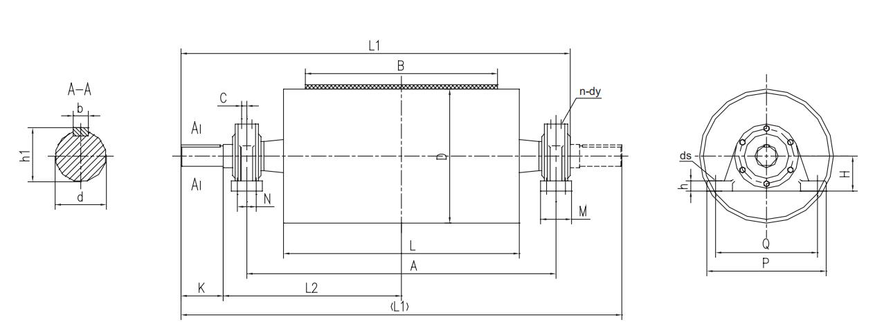
Unit: mm
| B | D | Allowable torque (KN·m) | Allowable resultant force (KN) | Drawing No | A | L | L1 | L2 | K | M | N | Q | P | H | h | h1 | d | b | ds | C | n-dy |
| 500 | 500 | 2.7 | 49 | DTII01A4081 | 850 | 600 | 1114 | 495 | 140 | 70 | 350 | 410 | 120 | 33 | 74.5 | 70 | 20 | M20 | 22 | 2-M8×1 | |
| DTII01A4083YZ | |||||||||||||||||||||
| DTII01A4084 | |||||||||||||||||||||
| 650 | 3.5 | 40 | DTII02A4081 | 1000 | 750 | 1264 | 570 | ||||||||||||||
| DTII02A4083YZ | |||||||||||||||||||||
| DTII02A4084 | |||||||||||||||||||||
| 630 | 4.1 | DTII02A5081 | |||||||||||||||||||
| DTII02A5083YZ | |||||||||||||||||||||
| DTII02A5084 | |||||||||||||||||||||
| 500 | 6.3 | 59 | DTII02A4101 | 1324 | 590 | 170 | 80 | 380 | 460 | 135 | 46 | 95 | 90 | 25 | M24 | 26 | 4-M8×1 | ||||
| DTII02A4103YZ | |||||||||||||||||||||
| DTII02A4104 | |||||||||||||||||||||
| 630 | 7.3 | 80 | DTII02A5101 | ||||||||||||||||||
| DTII02A5103YZ | |||||||||||||||||||||
| DTII02A5104 | |||||||||||||||||||||
| 500 | 8 | 83 | DTII02A4121 | 1050 | 1419 | 615 | 210 | 110 | 440 | 530 | 155 | 116 | 110 | 28 | 32 | ||||||
| DTII02A4123YZ | |||||||||||||||||||||
| DTII02A4124 | |||||||||||||||||||||
| 630 | 8.3 | 86 | DTII02A5121 | ||||||||||||||||||
| DTII02A5123YZ | |||||||||||||||||||||
| DTII02A5124 |
| B | D | Allowable torque (KN•m) |
Allowable resultant force (KN) |
Drawing No | A | L | L1 | L2 | K | M | N | Q | P | H | h | h1 | d | b | ds | C | n-dy |
| 800 | 500 | 4.1 | 40 | DTⅡ03A4101 | 1300 | 950 | 1624 | 740 | 170 | 80 | - | 380 | 460 | 135 | 46 | 95 | 90 | 25 | M24 | 26 | 4-M8×1 |
| DTⅡ03A4103ZYZ | |||||||||||||||||||||
| DTⅡ03A4104 | |||||||||||||||||||||
| 630 | 6 | 50 | DTⅡ03A5101 | ||||||||||||||||||
| DTⅡ03A5103ZYZ | |||||||||||||||||||||
| DTⅡ03A5104 | |||||||||||||||||||||
| 800 | 7 | DTⅡ03A6103ZYZ | |||||||||||||||||||
| DTⅡ03A6104 | |||||||||||||||||||||
| 630 | 12 | 80 | DTⅡ03A5121 | 1669 | 210 | 110 | 440 | 530 | 155 | 116 | 110 | 28 | M30 | 32 | |||||||
| DTⅡ03A5123ZYZ | |||||||||||||||||||||
| DTⅡ03A5124 | |||||||||||||||||||||
| 800 | 12 | 80 | DTⅡ03A6123ZYZ | ||||||||||||||||||
| DTⅡ03A6124 | |||||||||||||||||||||
| 630 | 20 | 100 | DTⅡ03A5141 | 1724 | 750 | 250 | 120 | 480 | 570 | 170 | 63 | 137 | 130 | 32 | 37 | ||||||
| DTⅡ03A5143ZYZ | |||||||||||||||||||||
| DTⅡ03A5144 | |||||||||||||||||||||
| 2×16 | DTⅡ03A5143S | 2000 | 1500 | ||||||||||||||||||
| DTⅡ03A5144S | |||||||||||||||||||||
| 800 | 20 | 110 | DTⅡ03A6143ZYZ | 1724 | 750 | ||||||||||||||||
| DTⅡ03A6144 | |||||||||||||||||||||
| 2×16 | DTⅡ03A6143S | 2000 | 1500 | ||||||||||||||||||
| DTⅡ03A6144S | |||||||||||||||||||||
| 32 | 160 | DTⅡ03A6163ZYZ | 1400 | 1839 | 800 | 200 | 105 | 520 | 640 | 200 | 60 | 158 | 150 | 36 | 43 | 4-M10×1 | |||||
| DTⅡ03A6164 | |||||||||||||||||||||
| 2×23 | DTⅡ03A6163S | 2100 | 1600 | ||||||||||||||||||
| DTⅡ03A6164S | |||||||||||||||||||||
| 1000 | 630 | 6 | 40 | DTⅡ04A5103ZYZ | 1500 | 1150 | 1824 | 840 | 170 | 80 | _ | 380 | 460 | 135 | 46 | 95 | 90 | 25 | M24 | 26 | 4-M8×1 |
| DTⅡ04A5104 | |||||||||||||||||||||
| 12 | 73 | DTⅡ04A5123ZYZ | 1869 | 210 | 110 | 440 | 530 | 155 | 116 | 110 | 28 | 32 | |||||||||
| DTⅡ04A5124 | |||||||||||||||||||||
| 800 | DTⅡ04A6123ZYZ | ||||||||||||||||||||
| DTⅡ04A6124 | |||||||||||||||||||||
| 1000 | 80 | DTⅡ04A7123ZYZ | |||||||||||||||||||
| DTⅡ04A7124 | |||||||||||||||||||||
| 630 | 18 | 100 | DTⅡ04A5143ZYZ | 1924 | 850 | 250 | 120 | 480 | 570 | 170 | 63 | 137 | 130 | 32 | M30 | 37 | |||||
| DTⅡ04A5144 | |||||||||||||||||||||
| 2×15 | DTⅡ04A5143S | 2300 | 1700 | ||||||||||||||||||
| DTⅡ04A5144S | |||||||||||||||||||||
| 800 | 20 | 110 | DTⅡ04A6143ZYZ | 1924 | 850 | ||||||||||||||||
| DTⅡ04A6144 | |||||||||||||||||||||
| 2×16 | DTⅡ04A6143S | 2300 | 1700 | ||||||||||||||||||
| DTⅡ04A6144S | |||||||||||||||||||||
| 1000 | 20 | 110 | DTⅡ04A7143ZYZ | 1924 | 850 | ||||||||||||||||
| DTⅡ04A7144 | |||||||||||||||||||||
| 2×16 | DTⅡ04A7143S | 2300 | 1700 | ||||||||||||||||||
| DTⅡ04A7144S |
| B | D | Allowable torque (KN•m) |
Allowable resultant force (KN) |
Drawing No | A | L | L1 | L2 | K | M | N | Q | P | H | h | h1 | d | b | ds | C | n-dy |
| 1000 | 800 | 27 | 160 | DTⅡ04A6163ZYZ | 1600 | 1150 | 2039 | 900 | 250 | 200 | 105 | 520 | 640 | 200 | 60 | 158 | 150 | 36 | M30 | 43 | 4-M10×1 |
| DTⅡ04A6164 | |||||||||||||||||||||
| 2×22 | DTⅡ04A6163S | 2300 | 1800 | ||||||||||||||||||
| DTⅡ04A6164S | |||||||||||||||||||||
| 1000 | 27 | 170 | DTⅡ04A7163ZYZ | 2039 | 900 | ||||||||||||||||
| DTⅡ04A7164 | |||||||||||||||||||||
| 2×22 | DTⅡ04A7163S | 2300 | 1800 | ||||||||||||||||||
| DTⅡ04A7164S | |||||||||||||||||||||
| 800 | 40 | 190 | DTⅡ04A6183ZYZ | 2110 | 910 | 300 | 220 | 120 | 570 | 700 | 220 | 70 | 179 | 170 | 40 | 46 | |||||
| DTⅡ04A6184 | |||||||||||||||||||||
| 2×35 | DTⅡ04A6183S | 2420 | 1820 | ||||||||||||||||||
| DTⅡ04A6184S | |||||||||||||||||||||
| 1000 | 40 | 210 | DTⅡ04A7183ZYZ | 2110 | 910 | ||||||||||||||||
| DTⅡ04A7184 | |||||||||||||||||||||
| 2×35 | DTⅡ04A7183S | 2420 | 1820 | ||||||||||||||||||
| DTⅡ04A7184S | |||||||||||||||||||||
| 800 | 50 | 300 | DTⅡ04A6203ZYZ | 1650 | 2278 | 975 | 350 | 240 | 140 | 640 | 780 | 240 | 75 | 200 | 190 | 45 | 60 | ||||
| DTⅡ04A6204 | |||||||||||||||||||||
| 2×40 | DTⅡ04A6203S | 2650 | 1950 | ||||||||||||||||||
| DTⅡ04A6204S | |||||||||||||||||||||
| 1000 | 52 | 330 | DTⅡ04A7203ZYZ | 2278 | 975 | ||||||||||||||||
| DTⅡ04A7204 | |||||||||||||||||||||
| 2×42 | DTⅡ04A7203S | 2650 | 1950 | ||||||||||||||||||
| DTⅡ04A7204S | |||||||||||||||||||||
| 1200 | 630 | 12 | 52 | DTⅡ05A5123ZYZ | 1750 | 1400 | 2129 | 975 | 210 | 110 | — | 440 | 530 | 155 | 46 | 116 | 110 | 28 | M24 | 32 | 4-M8×1 |
| DTⅡ05A5124 | |||||||||||||||||||||
| 800 | 80 | DTⅡ05A6123ZYZ | |||||||||||||||||||
| DTⅡ05A6124 | |||||||||||||||||||||
| 1000 | DTⅡ05A7123ZYZ | ||||||||||||||||||||
| DTⅡ05A7124 | |||||||||||||||||||||
| 630 | 20 | 85 | DTⅡ05A5143ZYZ | 1750 | 1400 | 2174 | 975 | 250 | 120 | — | 480 | 570 | 170 | 63 | 137 | 130 | 32 | M30 | 37 | 4-M8×1 | |
| DTⅡ05A5144 | |||||||||||||||||||||
| 2×16 | DTⅡ05A5143S | 2450 | 1950 | ||||||||||||||||||
| DTⅡ05A5144S | |||||||||||||||||||||
| 800 | 20 | 110 | DTⅡ05A6143ZYZ | 2174 | 975 | ||||||||||||||||
| DTⅡ05A6144 | |||||||||||||||||||||
| 2×16 | DTⅡ05A6143S | 2450 | 1950 | ||||||||||||||||||
| DTⅡ05A6144S | |||||||||||||||||||||
| 1000 | 20 | 110 | DTⅡ05A7143ZYZ | 2174 | 975 | ||||||||||||||||
| DTⅡ05A7144 | |||||||||||||||||||||
| 2×16 | DTⅡ05A7143S | 2450 | 1950 | ||||||||||||||||||
| DTⅡ05A7144S | |||||||||||||||||||||
| 800 | 27 | 140 | DTⅡ05A6163ZYZ | 1850 | 2289 | 1025 | 200 | 105 | 520 | 640 | 200 | 60 | 158 | 150 | 36 | 43 | 4-M10×1 | ||||
| DTⅡ05A6164 | |||||||||||||||||||||
| 2×22 | DTⅡ05A6163S | 2550 | 2050 | ||||||||||||||||||
| DTⅡ05A6164S |
| B | D | Allowable torque (KN•m) |
Allowable resultant force (KN) |
Drawing No | A | L | L1 | L2 | K | M | N | Q | P | H | h | h1 | d | b | ds | C | n-dy |
| 1200 | 1000 | 27 | 160 | DTⅡ05A7163ZYZ | 1850 | 1400 | 2289 | 1025 | 250 | 200 | 105 | 520 | 640 | 200 | 60 | 158 | 150 | 36 | M30 | 43 | 4-M10×1 |
| DTⅡ05A7164 | |||||||||||||||||||||
| 2×22 | DTⅡ05A7163S | 2550 | 2050 | ||||||||||||||||||
| DTⅡ05A7164S | |||||||||||||||||||||
| 800 | 40 | 180 | DTⅡ05A6183ZYZ | 2360 | 1035 | 300 | 220 | 120 | 570 | 700 | 220 | 70 | 179 | 170 | 40 | 46 | |||||
| DTⅡ05A6184 | |||||||||||||||||||||
| 2×32 | DTⅡ05A6183S | 2670 | 2070 | ||||||||||||||||||
| DTⅡ05A6184S | |||||||||||||||||||||
| 1000 | 40 | 210 | DTⅡ05A7183ZYZ | 2360 | 1035 | 300 | 220 | 120 | 570 | 700 | 220 | 70 | 179 | 170 | 40 | 46 | |||||
| DTⅡ05A7184 | |||||||||||||||||||||
| 2×32 | DTⅡ05A7183S | 2670 | 2070 | ||||||||||||||||||
| DTⅡ05A7184S | |||||||||||||||||||||
| 800 | 52 | 230 | DTⅡ05A6203ZYZ | 1900 | 2528 | 1100 | 350 | 240 | 140 | 640 | 780 | 240 | 75 | 200 | 190 | 45 | 60 | ||||
| DTⅡ05A6204 | |||||||||||||||||||||
| 2×42 | DTⅡ05A6203S | 2900 | 2200 | ||||||||||||||||||
| DTⅡ05A6204S | |||||||||||||||||||||
| 1000 | 52 | 290 | DTⅡ05A7203ZYZ | 2528 | 1100 | ||||||||||||||||
| DTⅡ05A7204 | |||||||||||||||||||||
| 2×42 | DTⅡ05A7203S | 2900 | 2200 | ||||||||||||||||||
| DTⅡ05A7204S | |||||||||||||||||||||
| 66 | 330 | DTⅡ05A7223ZYZ | 2533 | 1100 | 250 | 720 | 880 | 270 | 80 | 210 | 200 | M36 | 65 | ||||||||
| DTⅡ05A7224 | |||||||||||||||||||||
| 2×50 | DTⅡ05A7223S | 2900 | 2200 | ||||||||||||||||||
| DTⅡ05A7224S | |||||||||||||||||||||
| 1400 | 800 | 20 | 100 | DTⅡ06A6143ZYZ | 2050 | 1600 | 2474 | 1125 | 250 | 120 | — | 480 | 570 | 170 | 63 | 137 | 130 | 32 | M30 | 37 | 4-M8X1 |
| DTⅡ06A6144 | |||||||||||||||||||||
| 2×16 | DTⅡ06A6143S | 2750 | 2250 | ||||||||||||||||||
| DTⅡ06A6144S | |||||||||||||||||||||
| 1000 | 20 | DTⅡ06A7143ZYZ | 2474 | 1125 | |||||||||||||||||
| DTⅡ06A7144 | |||||||||||||||||||||
| 2×16 | DTⅡ06A7143S | 2750 | 2250 | ||||||||||||||||||
| DTⅡ06A7144S | |||||||||||||||||||||
| 800 | 27 | 130 | DTⅡ06A6163ZYZ | 2489 | 1125 | 200 | 105 | 520 | 640 | 200 | 60 | 158 | 150 | 36 | 43 | 4-M10×1 | |||||
| DTⅡ06A6164 | |||||||||||||||||||||
| 1000 | 27 | 160 | DTⅡ06A7163ZYZ | ||||||||||||||||||
| DTⅡ06A7164 | |||||||||||||||||||||
| 2×22 | DTⅡ06A7163S | 2750 | 2250 | ||||||||||||||||||
| DTⅡ06A7164S | |||||||||||||||||||||
| 800 | 40 | 170 | DTⅡ06A6183ZYZ | 2560 | 1135 | 300 | 220 | 120 | 570 | 700 | 220 | 70 | 179 | 170 | 40 | 46 | |||||
| DTⅡ06A6184 | |||||||||||||||||||||
| 2×32 | DTⅡ06A6183S | 2870 | 2270 | ||||||||||||||||||
| DTⅡ06A6184S | |||||||||||||||||||||
| 1000 | 40 | 210 | DTⅡ06A7183ZYZ | 2560 | 1135 | ||||||||||||||||
| DTⅡ06A7184 | |||||||||||||||||||||
| 2×32 | DTⅡ06A7183S | 2870 | 2270 | ||||||||||||||||||
| DTⅡ06A7184S |
| B | D | Allowable torque (KN•m) |
Allowable resultant force (KN) |
Drawing No | A | L | L1 | L2 | K | M | N | Q | P | H | h | h1 | d | b | ds | C | n-dy |
| 1400 | 800 | 52 | 210 | DTⅡ06A6203ZYZ | 2100 | 1600 | 2728 | 1200 | 350 | 240 | 140 | 640 | 780 | 240 | 75 | 200 | 190 | 45 | M30 | 60 | 4-M10×1 |
| DTⅡ06A6204 | |||||||||||||||||||||
| 2×42 | DTⅡ06A6203S | 3100 | 2400 | ||||||||||||||||||
| DTⅡ06A6204S | |||||||||||||||||||||
| 1000 | 52 | 260 | DTⅡ06A7203ZYZ | 2728 | 1200 | ||||||||||||||||
| DTⅡ06A7204 | |||||||||||||||||||||
| 2×42 | DTⅡ06A7203S | 3100 | 2400 | ||||||||||||||||||
| DTⅡ06A7204S | |||||||||||||||||||||
| 66 | 300 | DTⅡ06A7223ZYZ | 2733 | 1200 | 250 | 720 | 880 | 270 | 80 | 210 | 200 | M36 | 65 | ||||||||
| DTⅡ06A7224 | |||||||||||||||||||||
| 2×50 | DTⅡ06A7223S | 3100 | 2400 | ||||||||||||||||||
| DTⅡ06A7224S |
Note:
1. Y- Right single output axis, Z - Left single output axis, S - Dual output axis.
2. The last digit of the drawing number is "1" indicating a smooth surface, "3" indicating a herringbone adhesive surface, and "4" indicating a diamond adhesive surface.
technological innovation, keep improving
With ingenuity, we are committed to global sustainable development.
Professional Conveyor Manufacturer, Since 1998.
Mobile QR Code
News & Updates
Contact infor.
 Phone / Whatsapp:
 Tel: +86-0519-86511555
 E-mail: david@wuyunconveyor.com
 Add: No.16 Xinfa Road, Wujin District, Changzhou City, Jiangsu Province, China

 English