

E-mail:
david@wuyunconveyor.com

REQUEST A QUOTE
ENG
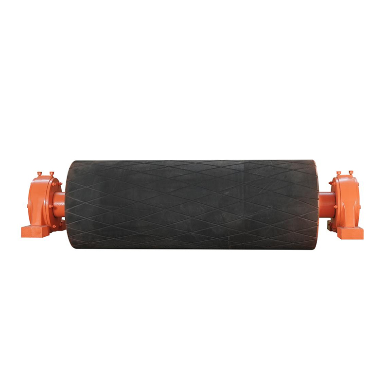
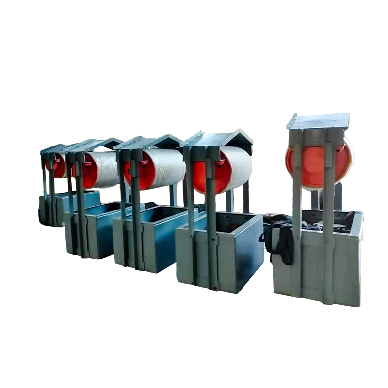
The Conveyor Take-Up Pulley is used in belt conveyor systems to maintain proper conveyor belt tension during operation. It helps compensate for belt elongation and maintain stable belt contact, reducing the risk of belt slipping and excessive belt sagging.
The pulley is designed with a high-strength steel drum and can be equipped with rubber, ceramic, or polyurethane lagging to increase surface friction and wear resistance. It can be integrated with gravity, screw, hydraulic, or combined take-up systems according to conveyor design requirements.
Key Features
Stable Belt Tension
The take-up pulley works within the tensioning arrangement to maintain appropriate belt tension and support stable conveyor operation.
Belt Elongation Compensation
The take-up system accommodates changes in belt length during operation, helping maintain consistent belt tension.
Multiple Take-Up Methods
The pulley can be used with gravity, screw/mechanical, hydraulic, or combined take-up arrangements to suit different conveyor configurations.
Multiple Lagging Options
Rubber, ceramic, and polyurethane lagging are available to increase friction and improve wear resistance.
Heavy-Duty Construction
A high-strength steel drum and heavy-duty bearings provide a robust foundation for continuous conveyor operation.
Product Advantages
Maintains belt tension: Helps prevent excessive belt sagging and belt slippage during conveyor operation.
Compensates for belt elongation: Supports stable belt tension as the conveyor belt changes in length during service.
Flexible system integration: Compatible with different take-up arrangements, including gravity, screw, and hydraulic systems.
Improved belt traction: Optional lagging increases friction between the pulley surface and conveyor belt.
Durable operation: High-strength construction and heavy-duty bearings support continuous conveyor service.
Easy maintenance: The robust pulley arrangement is designed for practical inspection and maintenance.
Applications
The Conveyor Take-Up Pulley is used in belt conveyor systems where controlled belt tension is required to maintain stable conveying performance. It is particularly suitable for conveyor installations where belt elongation, tension variation, or belt sagging needs to be accommodated during continuous operation.
Typical applications include:
Mining and Quarrying: Used in long or continuously operating conveyor systems handling ores, aggregates, and other bulk materials.
Coal Handling: Suitable for conveyor systems requiring stable belt tension during continuous bulk material transportation.
Cement and Building Materials: Used in bulk material conveying systems where consistent belt tension is important for reliable operation.
Steel and Metallurgy: Suitable for heavy-duty conveyor systems requiring durable tensioning components.
Ports and Bulk Material Terminals: Used in continuous conveyor systems where belt tension must be maintained over extended conveying routes.
General Bulk Material Handling: Applicable to belt conveyor systems using gravity, mechanical, hydraulic, or combined take-up arrangements.
Ordering & Quotation Information
Information Required for Quotation
Please provide the pulley diameter, face width, shaft dimensions, conveyor belt width, installation position, required quantity, and operating conditions. Information about the take-up arrangement and belt tension requirements should also be provided.
Technical Confirmation & Lead Time
We will confirm the take-up pulley according to the tensioning arrangement, belt tension requirements, pulley dimensions, shaft configuration, lagging requirements, and installation interface. Lead time is determined by specifications, quantity, material preparation, and purchased components.
Packaging, Delivery & Quality
Packaging and delivery are arranged according to pulley dimensions, weight, quantity, transportation method, and destination. Product dimensions, shaft configuration, surface condition, quantity, and packaging are checked before shipment.
FAQ
What is a Conveyor Take-Up Pulley?
A Conveyor Take-Up Pulley is a pulley used as part of a conveyor belt tensioning arrangement to maintain appropriate belt tension and compensate for changes in belt length during operation.
What is the main function of a take-up pulley?
Its main function is to work with the take-up system to maintain proper belt tension, helping reduce belt sagging and belt slippage.
What take-up systems can be used with the pulley?
According to the provided information, the available arrangements include gravity, screw/mechanical, hydraulic, and combined take-up systems.
Can a take-up pulley be lagged?
Yes. The provided product information specifies rubber, ceramic, and polyurethane lagging options for increasing friction and wear resistance.
How does a take-up system compensate for belt elongation?
The take-up arrangement adjusts the pulley position or tensioning force to accommodate changes in belt length, helping maintain appropriate operating tension.
What is the difference between a take-up pulley and a drive pulley?
A drive pulley provides the driving force that moves the conveyor belt, while a take-up pulley works within the tensioning system to maintain appropriate belt tension.
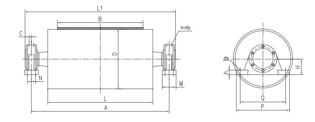
|
B |
Allowable resultant force (kN) |
D |
Bearing model |
A |
L |
L1 |
Q |
P |
H |
h |
M |
N |
ds |
C |
N-dy |
Smooth surface |
Adhesive surface |
||
|
Moment of inertia (kg·m²) |
Drawing No |
Moment of inertia (kg·m²) |
Drawing No |
||||||||||||||||
|
500 |
9 |
250 |
1310 |
850 |
600 |
945 |
260 |
320 |
90 |
33 |
70 |
— |
M16 |
14 |
2—M8×1 |
0.5 |
DTⅡ01B1051 |
|
|
|
10 |
315 |
1.3 |
DTⅡ01B2051 |
|
|
||||||||||||||
|
400 |
3 |
DTⅡ01B3051 |
3.5 |
DTⅡ01B3052 |
|||||||||||||||
|
23 |
1312 |
953 |
280 |
340 |
100 |
18 |
3 |
DTⅡ01B3061 |
3.5 |
DTⅡ01B3062 |
|||||||||
|
28 |
500 |
5 |
DTⅡ01B4061 |
6 |
DTⅡ01B4062 |
||||||||||||||
|
49 |
1316 |
959 |
350 |
410 |
120 |
M20 |
22 |
5 |
DTⅡ01B4081 |
6 |
DTⅡ01B4082 |
||||||||
|
650 |
8 |
250 |
1310 |
1000 |
750 |
1095 |
260 |
320 |
90 |
M16 |
14 |
0.8 |
DTⅡ02B1051 |
|
|
||||
|
315 |
1.5 |
DTⅡ02B2051 |
|
|
|||||||||||||||
|
16 |
1312 |
1103 |
280 |
340 |
100 |
18 |
1.8 |
DTⅡ02B2061 |
|
|
|||||||||
|
20 |
400 |
3 |
DTⅡ02B3061 |
3.5 |
DTⅡ02B3062 |
||||||||||||||
|
26 |
315 |
1316 |
1109 |
350 |
410 |
120 |
M20 |
22 |
2 |
DTⅡ02B2081 |
|
|
|||||||
|
32 |
400 |
3.3 |
DTⅡ02B3081 |
3.8 |
DTⅡ02B3082 |
||||||||||||||
|
40 |
500 |
6.5 |
DTⅡ02B4081 |
7.8 |
DTⅡ02B4082 |
||||||||||||||
|
46 |
400 |
3520 |
1129 |
380 |
460 |
135 |
46 |
80 |
M24 |
26 |
4—M8×1 |
3.5 |
DTⅡ02B3101 |
4 |
DTⅡ02B3102 |
||||
|
59 |
500 |
6.5 |
DTⅡ02B4101 |
7.8 |
DTⅡ02B4102 |
||||||||||||||
|
630 |
16.3 |
DTⅡ02B5101 |
18.5 |
DTⅡ02B5102 |
|||||||||||||||
|
70 |
3524 |
1050 |
1189 |
440 |
530 |
155 |
110 |
32 |
20.3 |
DTⅡ02B5121 |
21.3 |
DTⅡ02B5122 |
|||||||
|
800 |
6 |
250 |
1310 |
1250 |
950 |
1345 |
260 |
320 |
90 |
33 |
70 |
M16 |
14 |
2—M8×1 |
0.8 |
DTⅡ03B1051 |
|
|
|
|
12 |
315 |
1312 |
1353 |
280 |
340 |
100 |
18 |
1.5 |
DTⅡ03B2061 |
|
|
||||||||
|
20 |
1316 |
1359 |
350 |
410 |
120 |
M20 |
22 |
1.8 |
DTⅡ03B2081 |
|
|
||||||||
|
400 |
4.5 |
DTⅡ03B3081 |
4.8 |
DTⅡ03B3082 |
|||||||||||||||
|
32 |
3520 |
1300 |
1429 |
380 |
460 |
135 |
46 |
80 |
M24 |
26 |
4—M8×1 |
4.8 |
DTⅡ03B3101 |
5 |
DTⅡ03B3102 |
||||
|
40 |
500 |
7.8 |
DTⅡ03B4101 |
9.8 |
DTⅡ03B4102 |
||||||||||||||
|
50 |
630 |
19.5 |
DTⅡ03B5101 |
23.5 |
DTⅡ03B5102 |
||||||||||||||
|
47 |
400 |
3524 |
1439 |
440 |
530 |
155 |
110 |
32 |
5.5 |
DTⅡ03B3121 |
6.3 |
DTⅡ03B3122 |
|||||||
|
56 |
500 |
7.8 |
DTⅡ03B4121 |
9.3 |
DTⅡ03B4122 |
||||||||||||||
|
73 |
630 |
24.3 |
DTⅡ03B5121 |
49.5 |
DTⅡ03B5122 |
||||||||||||||
|
90 |
800 |
49.8 |
DTⅡ03B6121 |
57.3 |
DTⅡ03B6122 |
||||||||||||||
|
100 |
630 |
3528 |
1449 |
480 |
570 |
170 |
63 |
120 |
— |
M30 |
37 |
27.8 |
DTⅡ03B5141 |
30.8 |
DTⅡ03B5142 |
||||
|
126 |
800 |
54.8 |
DTⅡ03B6141 |
61.8 |
DTⅡ03B6142 |
||||||||||||||
|
170 |
630 |
3532 |
1400 |
1579 |
520 |
640 |
200 |
60 |
200 |
105 |
43 |
4-M10×1 |
30 |
DTⅡ03B5161 |
33 |
DTⅡ03B5162 |
|||
|
800 |
60.5 |
DTⅡ03B6161 |
67.5 |
DTⅡ03B6162 |
|||||||||||||||
|
240 |
1000 |
125.3 |
DTⅡ03B7161 |
140 |
DTⅡ03B7162 |
||||||||||||||
|
250 |
800 |
3536 |
1601 |
570 |
700 |
220 |
70 |
220 |
120 |
46 |
61.8 |
DTⅡ03B6181 |
68.8 |
DTⅡ03B6182 |
|||||
|
330 |
1000 |
126.5 |
DTⅡ03B7181 |
140.3 |
DTⅡ03B7182 |
||||||||||||||
| B | Allowable resultant force (kN) |
D | Bearing model |
A | L | L1 | Q | P | H | h | M | N | ds | C | N-dy | Smooth surface | Adhesive surface | ||
| Moment of inertia (kg·m²) |
Drawing No | Moment of inertia (kg·m²) |
Drawing No | ||||||||||||||||
| 1000 | 6 | 250 | 1310 | 1450 | 1150 | 1545 | 260 | 320 | 90 | 33 | 70 | — | M16 | 14 | 2-M8×1 | 1 | DTⅡ04B1051 | ||
| 11 | 315 | 1312 | 1553 | 280 | 340 | 100 | 18 | 1.8 | DTⅡ04B2061 | ||||||||||
| 18 | 1316 | 1559 | 350 | 410 | 120 | M20 | 22 | 2 | DTⅡ04B2081 | ||||||||||
| 400 | 5 | DTⅡ04B3081 | 6 | DTⅡ04B3082 | |||||||||||||||
| 29 | 3520 | 1500 | 1629 | 380 | 460 | 135 | 46 | 80 | M24 | 26 | 4-M8×1 | 5 | DTⅡ04B3101 | 6 | DTⅡ04B3102 | ||||
| 35 | 500 | 11.5 | DTⅡ04B4101 | 13.3 | DTⅡ04B4102 | ||||||||||||||
| 43 | 630 | 23 | DTⅡ04B5101 | 26.5 | DTⅡ04B5102 | ||||||||||||||
| 45 | 400 | 3524 | 1639 | 440 | 530 | 155 | 110 | 32 | 7.3 | DTⅡ04B3121 | 8.3 | DTⅡ04B3122 | |||||||
| 500 | 9.5 | DTⅡ04B4121 | 11.3 | DTⅡ04B4122 | |||||||||||||||
| 64 | 630 | 29.8 | DTⅡ04B5121 | 33.3 | DTⅡ04B5122 | ||||||||||||||
| 79 | 800 | 58.3 | DTⅡ04B6121 | 67 | DTⅡ04B6122 | ||||||||||||||
| 75 | 500 | 3528 | 1649 | 480 | 570 | 170 | 63 | 120 | M30 | 37 | 8.5 | DTⅡ04B4141 | 9.8 | DTⅡ04B4142 | |||||
| 87 | 630 | 32.5 | DTⅡ04B5141 | 36 | DTⅡ04B5142 | ||||||||||||||
| 110 | 800 | 64.3 | DTⅡ04B6141 | 73 | DTⅡ04B6142 | ||||||||||||||
| 130 | 1000 | 1150 | — | 131.5 | DTⅡ04B7141 | 150.8 | DTⅡ04B7142 | ||||||||||||
| 168 | 630 | 3532 | 1600 | 1579 | 520 | 640 | 200 | 60 | 200 | 105 | 43 | 4-M10×1 | 10 | DTⅡ04B5161 | 38.5 | DTⅡ04B5162 | |||
| 800 | 73.3 | DTⅡ04B6161 | 81.8 | DTⅡ04B6162 | |||||||||||||||
| 200 | 1000 | 151.5 | DTⅡ04B7161 | 168.3 | DTⅡ04B7162 | ||||||||||||||
| 220 | 800 | 3536 | 1801 | 570 | 700 | 220 | 70 | 220 | 120 | 46 | 74.8 | DTⅡ04B6181 | 83.3 | DTⅡ04B6182 | |||||
| 290 | 1000 | 153.3 | DTⅡ04B7181 | 170 | DTⅡ04B7182 | ||||||||||||||
| 387 | 3540 | 1650 | 1906 | 640 | 780 | 240 | 75 | 240 | 140 | 60 | 198.5 | DTⅡ04B7201 | 215.3 | DTⅡ04B7202 | |||||
| 429 | 3544 | 1916 | 720 | 880 | 270 | 80 | 250 | M36 | 65 | 215.8 | DTⅡ04B7221 | 232.5 | DTⅡ04B7222 | ||||||
| 1200 | 6 | 250 | 1310 | 1700 | 1400 | 1795 | 260 | 320 | 90 | 33 | 70 | — | M16 | 14 | 2-M8×1 | 1.3 | DTⅡ05B1051 | ||
| 11 | 315 | 1312 | 1803 | 280 | 340 | 100 | 18 | 1.8 | DTⅡ05B2061 | ||||||||||
| 17 | 1316 | 1809 | 350 | 410 | 120 | M20 | 22 | 2 | DTⅡ05B2081 | ||||||||||
| 400 | 6 | DTⅡ05B3081 | 7 | DTⅡ05B3082 | |||||||||||||||
| 26 | 3520 | 1750 | 1879 | 380 | 460 | 135 | 46 | 80 | M24 | 26 | 4-M8×1 | 7 | DTⅡ05B3102 | ||||||
| 30 | 500 | 16.3 | DTⅡ05B4102 | ||||||||||||||||
| 37 | 630 | 32.3 | DTⅡ05B5102 | ||||||||||||||||
| 38 | 400 | 3524 | 1889 | 440 | 530 | 155 | 110 | 32 | 10 | DTⅡ05B3122 | |||||||||
| 41 | 500 | 13.8 | DTⅡ05B4122 | ||||||||||||||||
| 53 | 630 | 38 | DTⅡ05B5122 | ||||||||||||||||
| 64 | 800 | 79.5 | DTⅡ05B6122 | ||||||||||||||||
| 70 | 500 | 3528 | 1899 | 480 | 570 | 170 | 63 | 120 | M30 | 37 | 21 | DTⅡ05B4142 | |||||||
| 90 | 630 | 42.5 | DTⅡ05B5142 | ||||||||||||||||
| 100 | 800 | 87 | DTⅡ05B6142 | ||||||||||||||||
| 134 | 1000 | 175.8 | DTⅡ05B7142 | ||||||||||||||||
| 150 | 630 | 3532 | 1850 | 2029 | 520 | 640 | 200 | 60 | 200 | 105 | 43 | 4-M10×1 | 46.8 | DTⅡ05B5162 | |||||
| 800 | 99.5 | DTⅡ05B6162 | |||||||||||||||||
| 1000 | 204.8 | DTⅡ05B7162 | |||||||||||||||||
| 200 | 800 | 3536 | 2051 | 570 | 700 | 220 | 70 | 220 | 120 | 46 | 101.3 | DTⅡ05B6182 | |||||||
| 1000 | 207 | DTⅡ05B7182 | |||||||||||||||||
| 230 | 800 | 3540 | 1900 | 1400 | 2156 | 640 | 780 | 240 | 75 | 240 | 140 | M30 | 60 | 4-M10×1 | 118.3 | DTⅡ05B6202 | |||
| 351 | 1000 | 262 | DTⅡ05B7202 | ||||||||||||||||
| 391 | 3544 | 2166 | 720 | 880 | 270 | 80 | 250 | M36 | 65 | 283 | DTⅡ05B7222 | ||||||||
| 437 | 3548 | 2186 | 750 | 900 | 290 | 90 | 75 | 291 | DTⅡ05B7242 | ||||||||||
| B | Allowable resultant force (kN) |
D | Bearing model |
A | L | L1 | Q | P | H | h | M | N | ds | C | N-dy | Smooth surface | Adhesive surface | ||
| Moment of inertia (kg·m²) |
Drawing No | Moment of inertia (kg·m²) |
Drawing No | ||||||||||||||||
| 1400 | 17 | 315 | 1316 | 1900 | 1600 | 2009 | 350 | 410 | 120 | 33 | 70 | — | M20 | 22 | 4-M8×1 | 2.3 | DTⅡ06B2081 | ||
| 400 | 6.8 | DTⅡ06B3081 | 8 | DTⅡ06B3082 | |||||||||||||||
| 25 | 3520 | 1950 | 2079 | 380 | 460 | 135 | 46 | 80 | M24 | 26 | 4-M8×1 | 8 | DTⅡ06B3102 | ||||||
| 500 | 18.5 | DTⅡ06B4102 | |||||||||||||||||
| 40 | 400 | 3524 | 2089 | 440 | 530 | 155 | 110 | 32 | 11.5 | DTⅡ06B3122 | |||||||||
| 500 | 15.8 | DTⅡ06B4122 | |||||||||||||||||
| 50 | 630 | 42.8 | DTⅡ06B5122 | ||||||||||||||||
| 800 | 89.3 | DTⅡ06B6122 | |||||||||||||||||
| 66 | 500 | 3528 | 2050 | 1600 | 2199 | 480 | 570 | 170 | 63 | 120 | — | M30 | 37 | 24 | DTⅡ06B4142 | ||||
| 90 | 630 | 48 | DTⅡ06B5142 | ||||||||||||||||
| 94 | 800 | 98.3 | DTⅡ06B6142 | ||||||||||||||||
| 100 | 1000 | 198 | DTⅡ06B7142 | ||||||||||||||||
| 120 | 630 | 3532 | 2299 | 520 | 640 | 200 | 60 | 200 | 105 | 43 | 4-M10×1 | 53.5 | DTⅡ06B65162 | ||||||
| 150 | 800 | 113.8 | DTⅡ06B6162 | ||||||||||||||||
| 1000 | 234 | DTⅡ06B7162 | |||||||||||||||||
| 186 | 800 | 3536 | 2251 | 570 | 700 | 220 | 70 | 220 | 120 | 46 | 115.8 | DTⅡ06B6182 | |||||||
| 236 | 1000 | 236.5 | DTⅡ06B7182 | ||||||||||||||||
| 214 | 800 | 3540 | 2100 | 2356 | 640 | 780 | 240 | 75 | 240 | 140 | 60 | 135.3 | DTⅡ06B6202 | ||||||
| 331 | 1000 | 299.5 | DTⅡ06B7202 | ||||||||||||||||
| 361 | 3544 | 2366 | 720 | 880 | 270 | 80 | 250 | M36 | 65 | 300 | DTⅡ06B7222 | ||||||||
| 400 | 3548 | 2386 | 750 | 900 | 290 | 90 | 75 | 323.8 | DTⅡ06B7242 | ||||||||||
| 427 | 3552 | 2396 | 375.5 | DTⅡ06B7262 | |||||||||||||||
technological innovation, keep improving
With ingenuity, we are committed to global sustainable development.
Professional Conveyor Manufacturer, Since 1998.
Mobile QR Code
News & Updates
Contact infor.
 Phone / Whatsapp:
 Tel: +86-0519-86511555
 E-mail: david@wuyunconveyor.com
 Add: No.16 Xinfa Road, Wujin District, Changzhou City, Jiangsu Province, China

 English