

E-mail:
david@wuyunconveyor.com

REQUEST A QUOTE
ENG
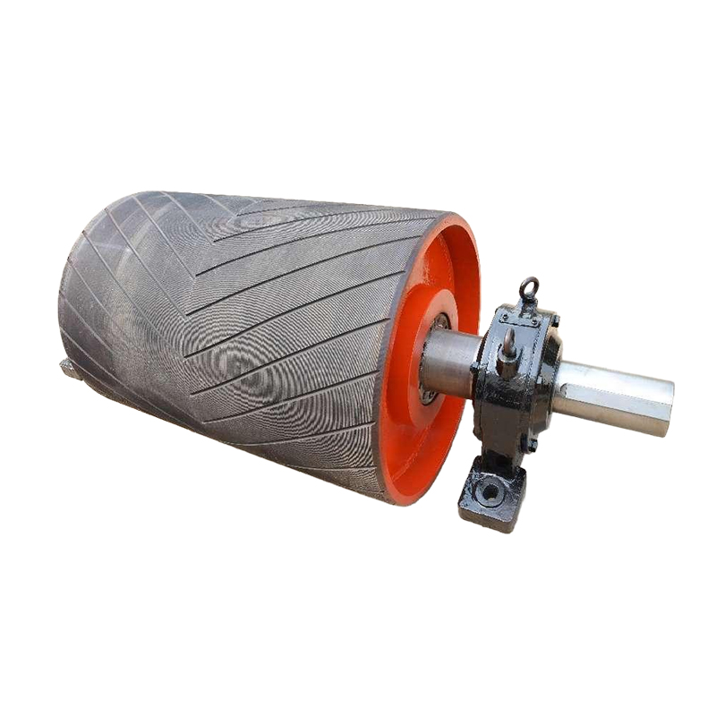
The Conveyor Drive Pulley is installed at the head of stationary belt conveyor systems to transmit driving force to the conveyor belt and support continuous bulk material conveying.
The pulley can be equipped with different lagging options, including cast rubber lagging, ceramic lagging, and polyurethane lagging, to increase surface friction and improve wear resistance according to operating requirements. Rubber lagging can also be supplied with diamond or V-shaped patterns to enhance belt grip.
With reliable bearing housing and sealing arrangements, the Conveyor Drive Pulley provides stable power transmission and dependable operation for demanding bulk material handling systems.
Key Features
Head Drive Application
Designed for installation at the head of stationary belt conveyors, the drive pulley provides the main driving contact between the conveyor belt and the drive system.
Multiple Lagging Options
Cast rubber, ceramic, and polyurethane lagging options allow the pulley surface to be selected according to friction and wear requirements.
Grooved Rubber Lagging
Diamond and V-shaped rubber patterns are available to increase belt-to-pulley grip and help reduce belt slippage during operation.
Flexible Bearing Housing Design
The bearing housing is available in integral or split configurations, providing different installation and maintenance options for conveyor systems.
Reliable Sealing and Lubrication
The bearing arrangement uses skeleton oil seals and lithium-based grease lubrication to help protect the bearing area and maintain reliable operation.
Product Advantages
Reliable power transmission: Provides effective driving contact between the pulley surface and conveyor belt.
Improved belt grip: Rubber, ceramic, and polyurethane lagging options help increase friction according to operating conditions.
Reduced belt slippage: Diamond and V-shaped rubber patterns improve traction between the pulley and belt.
Wear-resistant surface options: Different lagging materials provide flexibility for applications with different wear requirements.
Flexible bearing housing: Integral and split housing designs accommodate different conveyor installation requirements.
Reliable bearing protection: Sealing and lithium-based grease lubrication help maintain stable bearing operation.
Applications
The Conveyor Drive Pulley is used at the head of stationary belt conveyors for continuous transportation of bulk materials. Its lagging options make it suitable for conveyor systems where reliable belt traction, surface wear resistance, and stable power transmission are important.
Typical applications include:
Mining and Quarrying: Used in conveyor systems transporting ores, minerals, crushed stone, sand, and other bulk materials.
Metallurgy and Steel: Suitable for material handling systems requiring reliable drive components under continuous operating conditions.
Chemical Processing: Used in bulk material conveying systems where appropriate pulley surface protection and reliable operation are required.
Ports and Bulk Material Terminals: Suitable for conveyor systems handling large volumes of bulk materials over continuous conveying routes.
Papermaking: Used in industrial material conveying systems requiring stable belt drive performance.
General Bulk Material Handling: Suitable for stationary belt conveyors used to transport various bulk materials.
Ordering & Quotation Information
Information Required for Quotation
Please provide the pulley diameter, face width, shaft dimensions, conveyor belt width, installation position, required quantity, and operating conditions. Belt tension, lagging requirements, bearing housing requirements, and existing drawings or photos should be provided where applicable.
Technical Confirmation & Lead Time
We will confirm the drive pulley according to drive arrangement, belt tension, traction requirements, shaft arrangement, lagging, and installation interface. Lead time depends on specifications, quantity, material preparation, purchased components, and lagging requirements.
Packaging, Delivery & Quality
Packaging and delivery are arranged according to pulley dimensions, weight, quantity, transportation method, and destination. Dimensions, shaft configuration, lagging condition, quantity, and packaging are checked before shipment.
FAQ
What is a Conveyor Drive Pulley?
A Conveyor Drive Pulley is the primary driving pulley installed at the head of a belt conveyor. It transfers driving force to the conveyor belt to move the conveyed material.
Is a drive pulley also called a head pulley?
Yes. A drive pulley installed at the head of a conveyor is commonly referred to as a Head Pulley. The two terms are widely used in conveyor engineering and procurement.
What lagging options are available for the drive pulley?
The available options include cast rubber lagging, ceramic lagging, and polyurethane lagging. Rubber lagging can also use diamond or V-shaped patterns.
Why is lagging used on a drive pulley?
Lagging increases friction between the pulley surface and conveyor belt, helping improve traction and reduce belt slippage. Ceramic lagging is particularly useful where higher wear resistance and additional grip are required.
What rubber lagging patterns are available?
According to the provided product information, diamond and V-shaped patterns are available for cast rubber lagging.
What bearing housing options are available?
The drive pulley can use either an integral bearing housing or a split bearing housing, depending on the conveyor configuration and maintenance requirements.
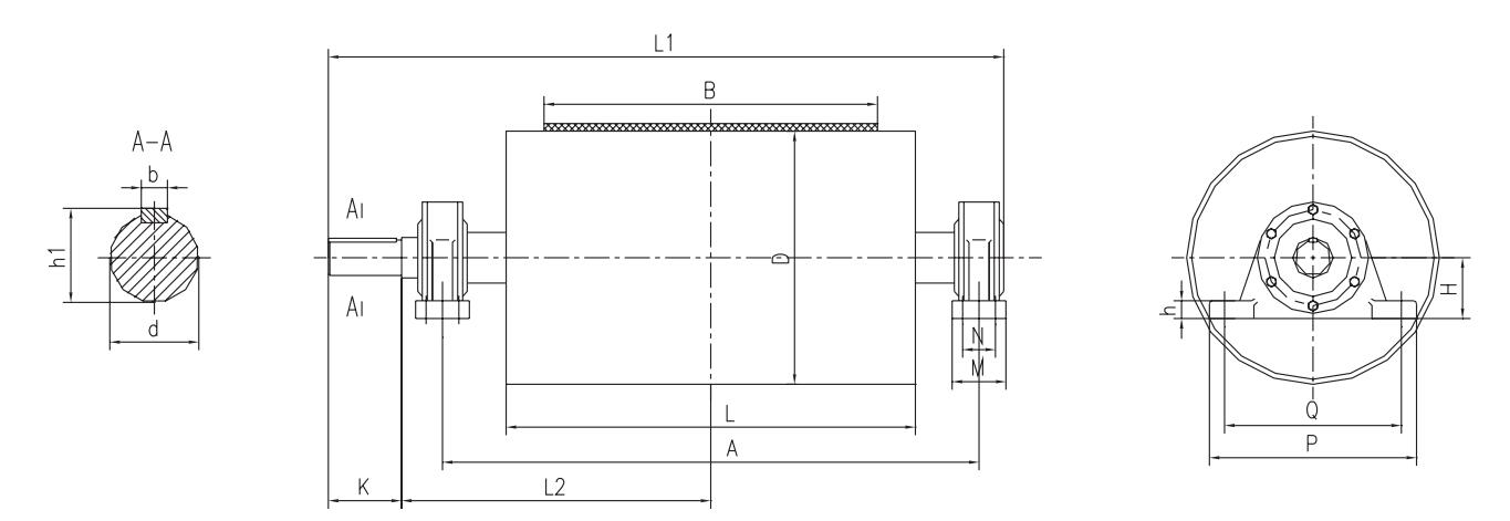
Unit: mm
| B | D | A | L | L1 | L2 | K | M | N | Q | P | H | h | h1 | d | b | ds | Bearing | Allowable torque (kg/mm) |
Drawing No | |||
| Smooth surface |
Adhesive surface |
Smooth surface |
Casting glue |
Coated with adhesive |
||||||||||||||||||
| 500 | 500 | 850 | 600 | 1097 | 505.5 | 115 | 70 | — | 280 | 340 | 100 | 33 | 60 | 55 | 16 | 27 | 1312 | 16300 | 25000 | TD1A13 | TD1A23 | TD1A33 |
| 650 | 500 | 1000 | 750 | 1280 | 588.5 | 135 | 90 | — | 350 | 410 | 120 | 33 | 76 | 70 | 20 | 1316 | 21200 | 32600 | TD2A13 | TD2A23 | TD2A33 | |
| 630 | 29600 | 45400 | TD2A14 | TD2A24 | TD2A34 | |||||||||||||||||
| 800 | 500 | 1300 | 950 | 1580 | 738.5 | 135 | 90 | — | 350 | 410 | 120 | 33 | 76 | 70 | 20 | 1316 | 26200 | 40100 | TD3A13 | TD3A23 | TD3A33 | |
| 630 | 1661 | 771 | 175 | 130 | 80 | 380 | 460 | 140 | 33 | 97 | 90 | 24 | 3520 | 36700 | 56100 | TD3A14 | TD3A24 | TD3A34 | ||||
| 800 | 55900 | 85500 | TD3A15 | TD3A25 | TD3A35 | |||||||||||||||||
| 1000 | 630 | 1500 | 1150 | 1861 | 871 | 175 | 130 | 80 | 380 | 460 | 140 | 33 | 97 | 90 | 24 | 3520 | 45700 | 70100 | TD4A14 | TD4A24 | TD4A34 | |
| 800 | 1945 | 900 | 215 | 160 | 90 | 440 | 530 | 160 | 53 | 119 | 110 | 32 | 34 | 3524 | 69600 | 106800 | TD4A15 | TD4A25 | TD4A35 | |||
| 1000 | 2020 | 930 | 255 | 170 | 100 | 480 | 570 | 180 | 53 | 140 | 130 | 36 | 3528 | 177500 | — | TD4A26 | TD4A36 | |||||
| 1200 | 630 | 1750 | 1400 | 2195 | 1025 | 215 | 160 | 90 | 440 | 530 | 160 | 53 | 119 | 110 | 32 | 3524 | 54900 | 84000 | TD5A14 | TD5A24 | TD5A34 | |
| 800 | 83700 | 128100 | TD5A15 | TD5A25 | TD5A35 | |||||||||||||||||
| 1000 | 2270 | 1055 | 255 | 170 | 100 | 480 | 570 | 180 | 53 | 140 | 130 | 36 | 3528 | 213000 | — | TD5A26 | TD5A36 | |||||
| 1250 | 2305 | 1065 | 275 | 180 | 110 | 540 | 630 | 200 | 63 | 161 | 150 | 40 | 3532 | 300000 | — | TD5A27 | TD5A37 | |||||
| 1400 | 800 | 2000 | 1600 | 2445 | 1150 | 215 | 160 | 90 | 440 | 530 | 160 | 53 | 119 | 110 | 32 | 3524 | 97600 | 149200 | TD6A15 | TD6A25 | TD6A35 | |
| 1000 | 2555 | 1190 | 275 | 180 | 110 | 540 | 630 | 200 | 63 | 161 | 150 | 40 | 3532 | 249250 | — | TD6A26 | TD6A36 | |||||
| 1250 | 350000 | — | TD6A27 | TD6A37 | ||||||||||||||||||
| 1400 | 2635 | 1200 | 335 | 200 | 120 | 590 | 680 | 220 | 63 | 181 | 170 | 40 | 3536 | 470000 | — | TD6A28 | TD6A38 | |||||
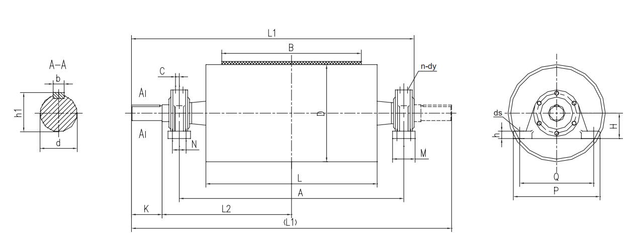
Unit: mm
| B | D | Allowable torque (KN·m) | Allowable resultant force (KN) | Drawing No | A | L | L1 | L2 | K | M | N | Q | P | H | h | h1 | d | b | ds | C | n-dy |
| 500 | 500 | 2.7 | 49 | DTII01A4081 | 850 | 600 | 1114 | 495 | 140 | 70 | 350 | 410 | 120 | 33 | 74.5 | 70 | 20 | M20 | 22 | 2-M8×1 | |
| DTII01A4083YZ | |||||||||||||||||||||
| DTII01A4084 | |||||||||||||||||||||
| 650 | 3.5 | 40 | DTII02A4081 | 1000 | 750 | 1264 | 570 | ||||||||||||||
| DTII02A4083YZ | |||||||||||||||||||||
| DTII02A4084 | |||||||||||||||||||||
| 630 | 4.1 | DTII02A5081 | |||||||||||||||||||
| DTII02A5083YZ | |||||||||||||||||||||
| DTII02A5084 | |||||||||||||||||||||
| 500 | 6.3 | 59 | DTII02A4101 | 1324 | 590 | 170 | 80 | 380 | 460 | 135 | 46 | 95 | 90 | 25 | M24 | 26 | 4-M8×1 | ||||
| DTII02A4103YZ | |||||||||||||||||||||
| DTII02A4104 | |||||||||||||||||||||
| 630 | 7.3 | 80 | DTII02A5101 | ||||||||||||||||||
| DTII02A5103YZ | |||||||||||||||||||||
| DTII02A5104 | |||||||||||||||||||||
| 500 | 8 | 83 | DTII02A4121 | 1050 | 1419 | 615 | 210 | 110 | 440 | 530 | 155 | 116 | 110 | 28 | 32 | ||||||
| DTII02A4123YZ | |||||||||||||||||||||
| DTII02A4124 | |||||||||||||||||||||
| 630 | 8.3 | 86 | DTII02A5121 | ||||||||||||||||||
| DTII02A5123YZ | |||||||||||||||||||||
| DTII02A5124 |
| B | D | Allowable torque (KN•m) |
Allowable resultant force (KN) |
Drawing No | A | L | L1 | L2 | K | M | N | Q | P | H | h | h1 | d | b | ds | C | n-dy |
| 800 | 500 | 4.1 | 40 | DTⅡ03A4101 | 1300 | 950 | 1624 | 740 | 170 | 80 | - | 380 | 460 | 135 | 46 | 95 | 90 | 25 | M24 | 26 | 4-M8×1 |
| DTⅡ03A4103ZYZ | |||||||||||||||||||||
| DTⅡ03A4104 | |||||||||||||||||||||
| 630 | 6 | 50 | DTⅡ03A5101 | ||||||||||||||||||
| DTⅡ03A5103ZYZ | |||||||||||||||||||||
| DTⅡ03A5104 | |||||||||||||||||||||
| 800 | 7 | DTⅡ03A6103ZYZ | |||||||||||||||||||
| DTⅡ03A6104 | |||||||||||||||||||||
| 630 | 12 | 80 | DTⅡ03A5121 | 1669 | 210 | 110 | 440 | 530 | 155 | 116 | 110 | 28 | M30 | 32 | |||||||
| DTⅡ03A5123ZYZ | |||||||||||||||||||||
| DTⅡ03A5124 | |||||||||||||||||||||
| 800 | 12 | 80 | DTⅡ03A6123ZYZ | ||||||||||||||||||
| DTⅡ03A6124 | |||||||||||||||||||||
| 630 | 20 | 100 | DTⅡ03A5141 | 1724 | 750 | 250 | 120 | 480 | 570 | 170 | 63 | 137 | 130 | 32 | 37 | ||||||
| DTⅡ03A5143ZYZ | |||||||||||||||||||||
| DTⅡ03A5144 | |||||||||||||||||||||
| 2×16 | DTⅡ03A5143S | 2000 | 1500 | ||||||||||||||||||
| DTⅡ03A5144S | |||||||||||||||||||||
| 800 | 20 | 110 | DTⅡ03A6143ZYZ | 1724 | 750 | ||||||||||||||||
| DTⅡ03A6144 | |||||||||||||||||||||
| 2×16 | DTⅡ03A6143S | 2000 | 1500 | ||||||||||||||||||
| DTⅡ03A6144S | |||||||||||||||||||||
| 32 | 160 | DTⅡ03A6163ZYZ | 1400 | 1839 | 800 | 200 | 105 | 520 | 640 | 200 | 60 | 158 | 150 | 36 | 43 | 4-M10×1 | |||||
| DTⅡ03A6164 | |||||||||||||||||||||
| 2×23 | DTⅡ03A6163S | 2100 | 1600 | ||||||||||||||||||
| DTⅡ03A6164S | |||||||||||||||||||||
| 1000 | 630 | 6 | 40 | DTⅡ04A5103ZYZ | 1500 | 1150 | 1824 | 840 | 170 | 80 | _ | 380 | 460 | 135 | 46 | 95 | 90 | 25 | M24 | 26 | 4-M8×1 |
| DTⅡ04A5104 | |||||||||||||||||||||
| 12 | 73 | DTⅡ04A5123ZYZ | 1869 | 210 | 110 | 440 | 530 | 155 | 116 | 110 | 28 | 32 | |||||||||
| DTⅡ04A5124 | |||||||||||||||||||||
| 800 | DTⅡ04A6123ZYZ | ||||||||||||||||||||
| DTⅡ04A6124 | |||||||||||||||||||||
| 1000 | 80 | DTⅡ04A7123ZYZ | |||||||||||||||||||
| DTⅡ04A7124 | |||||||||||||||||||||
| 630 | 18 | 100 | DTⅡ04A5143ZYZ | 1924 | 850 | 250 | 120 | 480 | 570 | 170 | 63 | 137 | 130 | 32 | M30 | 37 | |||||
| DTⅡ04A5144 | |||||||||||||||||||||
| 2×15 | DTⅡ04A5143S | 2300 | 1700 | ||||||||||||||||||
| DTⅡ04A5144S | |||||||||||||||||||||
| 800 | 20 | 110 | DTⅡ04A6143ZYZ | 1924 | 850 | ||||||||||||||||
| DTⅡ04A6144 | |||||||||||||||||||||
| 2×16 | DTⅡ04A6143S | 2300 | 1700 | ||||||||||||||||||
| DTⅡ04A6144S | |||||||||||||||||||||
| 1000 | 20 | 110 | DTⅡ04A7143ZYZ | 1924 | 850 | ||||||||||||||||
| DTⅡ04A7144 | |||||||||||||||||||||
| 2×16 | DTⅡ04A7143S | 2300 | 1700 | ||||||||||||||||||
| DTⅡ04A7144S |
| B | D | Allowable torque (KN•m) |
Allowable resultant force (KN) |
Drawing No | A | L | L1 | L2 | K | M | N | Q | P | H | h | h1 | d | b | ds | C | n-dy |
| 1000 | 800 | 27 | 160 | DTⅡ04A6163ZYZ | 1600 | 1150 | 2039 | 900 | 250 | 200 | 105 | 520 | 640 | 200 | 60 | 158 | 150 | 36 | M30 | 43 | 4-M10×1 |
| DTⅡ04A6164 | |||||||||||||||||||||
| 2×22 | DTⅡ04A6163S | 2300 | 1800 | ||||||||||||||||||
| DTⅡ04A6164S | |||||||||||||||||||||
| 1000 | 27 | 170 | DTⅡ04A7163ZYZ | 2039 | 900 | ||||||||||||||||
| DTⅡ04A7164 | |||||||||||||||||||||
| 2×22 | DTⅡ04A7163S | 2300 | 1800 | ||||||||||||||||||
| DTⅡ04A7164S | |||||||||||||||||||||
| 800 | 40 | 190 | DTⅡ04A6183ZYZ | 2110 | 910 | 300 | 220 | 120 | 570 | 700 | 220 | 70 | 179 | 170 | 40 | 46 | |||||
| DTⅡ04A6184 | |||||||||||||||||||||
| 2×35 | DTⅡ04A6183S | 2420 | 1820 | ||||||||||||||||||
| DTⅡ04A6184S | |||||||||||||||||||||
| 1000 | 40 | 210 | DTⅡ04A7183ZYZ | 2110 | 910 | ||||||||||||||||
| DTⅡ04A7184 | |||||||||||||||||||||
| 2×35 | DTⅡ04A7183S | 2420 | 1820 | ||||||||||||||||||
| DTⅡ04A7184S | |||||||||||||||||||||
| 800 | 50 | 300 | DTⅡ04A6203ZYZ | 1650 | 2278 | 975 | 350 | 240 | 140 | 640 | 780 | 240 | 75 | 200 | 190 | 45 | 60 | ||||
| DTⅡ04A6204 | |||||||||||||||||||||
| 2×40 | DTⅡ04A6203S | 2650 | 1950 | ||||||||||||||||||
| DTⅡ04A6204S | |||||||||||||||||||||
| 1000 | 52 | 330 | DTⅡ04A7203ZYZ | 2278 | 975 | ||||||||||||||||
| DTⅡ04A7204 | |||||||||||||||||||||
| 2×42 | DTⅡ04A7203S | 2650 | 1950 | ||||||||||||||||||
| DTⅡ04A7204S | |||||||||||||||||||||
| 1200 | 630 | 12 | 52 | DTⅡ05A5123ZYZ | 1750 | 1400 | 2129 | 975 | 210 | 110 | — | 440 | 530 | 155 | 46 | 116 | 110 | 28 | M24 | 32 | 4-M8×1 |
| DTⅡ05A5124 | |||||||||||||||||||||
| 800 | 80 | DTⅡ05A6123ZYZ | |||||||||||||||||||
| DTⅡ05A6124 | |||||||||||||||||||||
| 1000 | DTⅡ05A7123ZYZ | ||||||||||||||||||||
| DTⅡ05A7124 | |||||||||||||||||||||
| 630 | 20 | 85 | DTⅡ05A5143ZYZ | 1750 | 1400 | 2174 | 975 | 250 | 120 | — | 480 | 570 | 170 | 63 | 137 | 130 | 32 | M30 | 37 | 4-M8×1 | |
| DTⅡ05A5144 | |||||||||||||||||||||
| 2×16 | DTⅡ05A5143S | 2450 | 1950 | ||||||||||||||||||
| DTⅡ05A5144S | |||||||||||||||||||||
| 800 | 20 | 110 | DTⅡ05A6143ZYZ | 2174 | 975 | ||||||||||||||||
| DTⅡ05A6144 | |||||||||||||||||||||
| 2×16 | DTⅡ05A6143S | 2450 | 1950 | ||||||||||||||||||
| DTⅡ05A6144S | |||||||||||||||||||||
| 1000 | 20 | 110 | DTⅡ05A7143ZYZ | 2174 | 975 | ||||||||||||||||
| DTⅡ05A7144 | |||||||||||||||||||||
| 2×16 | DTⅡ05A7143S | 2450 | 1950 | ||||||||||||||||||
| DTⅡ05A7144S | |||||||||||||||||||||
| 800 | 27 | 140 | DTⅡ05A6163ZYZ | 1850 | 2289 | 1025 | 200 | 105 | 520 | 640 | 200 | 60 | 158 | 150 | 36 | 43 | 4-M10×1 | ||||
| DTⅡ05A6164 | |||||||||||||||||||||
| 2×22 | DTⅡ05A6163S | 2550 | 2050 | ||||||||||||||||||
| DTⅡ05A6164S |
| B | D | Allowable torque (KN•m) |
Allowable resultant force (KN) |
Drawing No | A | L | L1 | L2 | K | M | N | Q | P | H | h | h1 | d | b | ds | C | n-dy |
| 1200 | 1000 | 27 | 160 | DTⅡ05A7163ZYZ | 1850 | 1400 | 2289 | 1025 | 250 | 200 | 105 | 520 | 640 | 200 | 60 | 158 | 150 | 36 | M30 | 43 | 4-M10×1 |
| DTⅡ05A7164 | |||||||||||||||||||||
| 2×22 | DTⅡ05A7163S | 2550 | 2050 | ||||||||||||||||||
| DTⅡ05A7164S | |||||||||||||||||||||
| 800 | 40 | 180 | DTⅡ05A6183ZYZ | 2360 | 1035 | 300 | 220 | 120 | 570 | 700 | 220 | 70 | 179 | 170 | 40 | 46 | |||||
| DTⅡ05A6184 | |||||||||||||||||||||
| 2×32 | DTⅡ05A6183S | 2670 | 2070 | ||||||||||||||||||
| DTⅡ05A6184S | |||||||||||||||||||||
| 1000 | 40 | 210 | DTⅡ05A7183ZYZ | 2360 | 1035 | 300 | 220 | 120 | 570 | 700 | 220 | 70 | 179 | 170 | 40 | 46 | |||||
| DTⅡ05A7184 | |||||||||||||||||||||
| 2×32 | DTⅡ05A7183S | 2670 | 2070 | ||||||||||||||||||
| DTⅡ05A7184S | |||||||||||||||||||||
| 800 | 52 | 230 | DTⅡ05A6203ZYZ | 1900 | 2528 | 1100 | 350 | 240 | 140 | 640 | 780 | 240 | 75 | 200 | 190 | 45 | 60 | ||||
| DTⅡ05A6204 | |||||||||||||||||||||
| 2×42 | DTⅡ05A6203S | 2900 | 2200 | ||||||||||||||||||
| DTⅡ05A6204S | |||||||||||||||||||||
| 1000 | 52 | 290 | DTⅡ05A7203ZYZ | 2528 | 1100 | ||||||||||||||||
| DTⅡ05A7204 | |||||||||||||||||||||
| 2×42 | DTⅡ05A7203S | 2900 | 2200 | ||||||||||||||||||
| DTⅡ05A7204S | |||||||||||||||||||||
| 66 | 330 | DTⅡ05A7223ZYZ | 2533 | 1100 | 250 | 720 | 880 | 270 | 80 | 210 | 200 | M36 | 65 | ||||||||
| DTⅡ05A7224 | |||||||||||||||||||||
| 2×50 | DTⅡ05A7223S | 2900 | 2200 | ||||||||||||||||||
| DTⅡ05A7224S | |||||||||||||||||||||
| 1400 | 800 | 20 | 100 | DTⅡ06A6143ZYZ | 2050 | 1600 | 2474 | 1125 | 250 | 120 | — | 480 | 570 | 170 | 63 | 137 | 130 | 32 | M30 | 37 | 4-M8X1 |
| DTⅡ06A6144 | |||||||||||||||||||||
| 2×16 | DTⅡ06A6143S | 2750 | 2250 | ||||||||||||||||||
| DTⅡ06A6144S | |||||||||||||||||||||
| 1000 | 20 | DTⅡ06A7143ZYZ | 2474 | 1125 | |||||||||||||||||
| DTⅡ06A7144 | |||||||||||||||||||||
| 2×16 | DTⅡ06A7143S | 2750 | 2250 | ||||||||||||||||||
| DTⅡ06A7144S | |||||||||||||||||||||
| 800 | 27 | 130 | DTⅡ06A6163ZYZ | 2489 | 1125 | 200 | 105 | 520 | 640 | 200 | 60 | 158 | 150 | 36 | 43 | 4-M10×1 | |||||
| DTⅡ06A6164 | |||||||||||||||||||||
| 1000 | 27 | 160 | DTⅡ06A7163ZYZ | ||||||||||||||||||
| DTⅡ06A7164 | |||||||||||||||||||||
| 2×22 | DTⅡ06A7163S | 2750 | 2250 | ||||||||||||||||||
| DTⅡ06A7164S | |||||||||||||||||||||
| 800 | 40 | 170 | DTⅡ06A6183ZYZ | 2560 | 1135 | 300 | 220 | 120 | 570 | 700 | 220 | 70 | 179 | 170 | 40 | 46 | |||||
| DTⅡ06A6184 | |||||||||||||||||||||
| 2×32 | DTⅡ06A6183S | 2870 | 2270 | ||||||||||||||||||
| DTⅡ06A6184S | |||||||||||||||||||||
| 1000 | 40 | 210 | DTⅡ06A7183ZYZ | 2560 | 1135 | ||||||||||||||||
| DTⅡ06A7184 | |||||||||||||||||||||
| 2×32 | DTⅡ06A7183S | 2870 | 2270 | ||||||||||||||||||
| DTⅡ06A7184S |
| B | D | Allowable torque (KN•m) |
Allowable resultant force (KN) |
Drawing No | A | L | L1 | L2 | K | M | N | Q | P | H | h | h1 | d | b | ds | C | n-dy |
| 1400 | 800 | 52 | 210 | DTⅡ06A6203ZYZ | 2100 | 1600 | 2728 | 1200 | 350 | 240 | 140 | 640 | 780 | 240 | 75 | 200 | 190 | 45 | M30 | 60 | 4-M10×1 |
| DTⅡ06A6204 | |||||||||||||||||||||
| 2×42 | DTⅡ06A6203S | 3100 | 2400 | ||||||||||||||||||
| DTⅡ06A6204S | |||||||||||||||||||||
| 1000 | 52 | 260 | DTⅡ06A7203ZYZ | 2728 | 1200 | ||||||||||||||||
| DTⅡ06A7204 | |||||||||||||||||||||
| 2×42 | DTⅡ06A7203S | 3100 | 2400 | ||||||||||||||||||
| DTⅡ06A7204S | |||||||||||||||||||||
| 66 | 300 | DTⅡ06A7223ZYZ | 2733 | 1200 | 250 | 720 | 880 | 270 | 80 | 210 | 200 | M36 | 65 | ||||||||
| DTⅡ06A7224 | |||||||||||||||||||||
| 2×50 | DTⅡ06A7223S | 3100 | 2400 | ||||||||||||||||||
| DTⅡ06A7224S |
Note:
1. Y- Right single output axis, Z - Left single output axis, S - Dual output axis.
2. The last digit of the drawing number is "1" indicating a smooth surface, "3" indicating a herringbone adhesive surface, and "4" indicating a diamond adhesive surface.
technological innovation, keep improving
With ingenuity, we are committed to global sustainable development.
Professional Conveyor Manufacturer, Since 1998.
Mobile QR Code
News & Updates
Contact infor.
 Phone / Whatsapp:
 Tel: +86-0519-86511555
 E-mail: david@wuyunconveyor.com
 Add: No.16 Xinfa Road, Wujin District, Changzhou City, Jiangsu Province, China

 English